
Silicone Mold Shrinkage: What to Expect & How to Compensate
Silicone mold shrinkage is the gap between the cavity you cut and the part you get, and it is the most common reason a first article fails a dimensional check. The percentage is small — typically 1.5% to 3% — but on a 150 mm enclosure that is up to 4.5 mm of missing part, which is the difference between a snap fit and a rattle.
This guide covers what the number actually is, why LSR and HTV do not share it, how to measure your own compound instead of trusting a data sheet, and how to build the silicone mold shrinkage allowance into the tool before steel is cut.
What Silicone Mold Shrinkage Actually Is
Silicone mold shrinkage happens because curing changes the structure. Unvulcanized compound is a disordered mix of polymer chains and filler; cross-linking locks those chains into a network and pulls the mass inward. The denser the network, the more the part moves. Filler loading works the other way — more filler means less shrinkage — which is why two compounds of the same hardness can land at different rates.
Shrinkage is expressed as the difference between a cavity dimension and the same dimension on the finished part, as a percentage of the cavity:
Shrinkage % = (cavity dimension − part dimension) ÷ cavity dimension × 100
Two numbers get confused constantly, and the confusion costs tooling money:
| Term | What it describes | Where it comes from |
|---|---|---|
| Material shrinkage | The compound's inherent rate | The compound TDS, from a standard test plaque |
| Mold shrinkage | What your part actually did in production | Measured on your geometry, your cure, your tool |
| Post-shrinkage | Movement after demold and post-cure | Measured 24 hours later, and again after the oven cycle |
The TDS silicone mold shrinkage figure is a starting point, not a specification. It is measured on a plaque with a fixed thickness and a fixed cure, which is never your part. Treat it as the midpoint of a range and plan the tool around the range.
When you measure matters as much as what you measure. Silicone continues to move after demold as it cools and finishes relaxing. A part measured ten minutes out of the press will read smaller than the same part measured after 24 hours at 23°C, and a correction derived from the ten-minute reading will be too large. Condition the samples, then measure.
One citation note: most supplier data sheets quote linear shrinkage per ASTM D955, which is written for thermoplastic molding materials. Silicone suppliers use it by convention and the numbers are useful for comparison, but the standard is not an elastomer method. When you need to specify what the finished part must meet, the relevant document is a rubber tolerance standard, not a shrinkage test.

LSR vs HTV: Two Different Shrinkage Profiles
The two production routes for silicone parts do not carry the same silicone mold shrinkage, and the difference is not academic — it decides how much tolerance you can promise a customer.
| Process | Typical range | What drives it | Spread across batches | Best for |
|---|---|---|---|---|
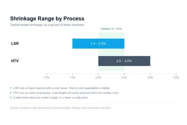
| LSR injection | 1.5% – 2.5% | Platinum addition cure, uniform network, tight filler control | Narrow, often ±0.1–0.2 points | Precision parts, multi-cavity tools, high volume |
| HTV compression | 2.0% – 3.0% | Peroxide cure, higher filler loading, mill-and-preform variation | Wider, batch and cavity dependent | Simple geometry, large single cavities, low volume |
The midpoint is the less important half of that table. What matters is the width of the spread: an LSR program can often be corrected once and left alone, while an HTV program may need per-cavity correction and a locked material batch because the compound itself moves between lots.
If a supplier quotes a single silicone mold shrinkage figure with no range and no process, ask which process and which compound. A number without those two facts is not a design input.
What Moves the Silicone Mold Shrinkage Number
Six variables account for most of the variation between a published silicone mold shrinkage value and a production part.
| Factor | How it moves the number | What to do |
|---|---|---|
| Hardness | Softer compounds generally shrink slightly more; the difference between 20A and 70A is often a few tenths of a percent | Confirm on your own hardness, not a table |
| Wall thickness | Thick sections cool slowly, keep curing after demold, and shrink more than thin walls | Design uniform walls; where impossible, compensate per zone |
| Cure temperature and time | More complete cure means more shrinkage, up to a plateau | Lock the cure profile before tool sign-off; never change it mid-run |
| Filler content | Higher silica loading reduces shrinkage | Take the figure from the exact grade, not the family |
| Demold temperature | Hot parts keep shrinking outside the tool | Control demold temperature, or allow for the extra movement |
| Post-cure | The oven cycle drives off volatiles and completes cure, so parts move again | Specify the cycle and measure after it, not before |
Two effects sit outside that table and cause most of the "same drawing, different result" arguments.
Direction. On long, thin or heavily filled parts, shrinkage along the flow path and across it are not identical. The difference is usually small in silicone compared with thermoplastics, but on a 200 mm strip it shows up as a length that is correct while the width is not.
Cavity position. In a multi-cavity tool, cavities near the platen edge run cooler than cavities in the centre. Cooler cavities cure less completely and shrink differently. This is why a tool that is dimensionally correct in cavity one can be out of tolerance in cavity eight.
For how hardness selection interacts with all of this, see our guide to silicone hardness Shore A — the same ±5A tolerance that applies to the hardness reading also applies to the shrinkage you can predict. That reading is taken with a durometer under ASTM D2240, which is worth citing when you compare two compounds' shrinkage claims.
How to Measure Your Own Shrinkage
Measuring silicone mold shrinkage takes four steps, and none of them require a production tool.
- Cut a soft tool. Aluminium or a 3D-printed cavity in the production geometry, or at minimum a plaque with a long dimension, a thin dimension and a hole pitch.
- Run it under production cure. Same compound, same temperature, same cycle. A sample cured differently tells you nothing about the production part.
- Condition for 24 hours at 23°C. Then post-cure if the production part gets post-cured, and measure again.
- Measure three features, not one. The longest dimension, the thinnest wall, and a hole or pin pitch. Compute each separately.
Use a calliper for a quick check on accessible external dimensions, and a CMM once the tolerance is tighter than ±0.1 mm or the feature cannot be reached directly. Measure the same feature on the cavity and on the part, and keep the temperature the same for both readings — a part measured cold reads smaller.
If you would rather see how a dimensional miss gets diagnosed in production, our case study on a custom rubber parts dimension fix walks through the measurement sequence.
Compensating in the 3D Model
There are three methods, and production tools usually use all three at once: uniform scaling for the bulk, feature-specific values for the critical details, and a steel-safe allowance for what nobody predicted.
Uniform Scaling
Enlarge the whole model by the measured rate:
Cavity dimension = target part dimension × (1 + shrinkage rate)
Uniform scaling is the fastest way to apply a silicone mold shrinkage allowance, and it works for parts whose only critical dimension is overall size. It fails on anything with a thread, a text callout, a snap fit or a mating bore, because scaling changes pitch and clearance along with size.
Feature-Specific Compensation
Apply individual values to the features that must fit something else:
- Threads — compensate the pitch diameter, never the pitch
- Snap fits and undercuts — compensate the interference, not the whole hook
- Port openings, button bosses and camera rings on an enclosure
- Hole and pin pitches — these scale with the part, so they need the full allowance
- Logos and text — leave at nominal; scaling distorts stroke width
An enclosure program is the clearest example: cutouts, camera rings and grip edges each carry their own correction, while the outer contour takes the uniform scale. That workflow is described in our tablet protective case silicone project.
Steel-Safe: Leave Stock and Cut After T1
The most reliable way to handle silicone mold shrinkage costs a little machining and saves a tool. Cut critical dimensions 0.1–0.2 mm per side oversize, run the first sample, measure the real shrinkage, then remove the stock. Steel can be taken away; it cannot be added back.
This is standard practice in serious tool rooms, and it is the reason a good mold maker will quote a T1 sample rather than promising a dimension from a data sheet. It also interacts with silicone mold cost — one extra machining pass is cheaper than a re-cut cavity.
Soft-Tool Sampling
For HTV, large parts, or any program where the shrinkage range is wide, build the soft tool, measure, adjust the model, then cut the production tool. It adds a week and removes most of the dimensional risk. The full pre-tooling review list is in our DFM checklist for silicone molds.
Worked Example: A 50 mm LSR Part
Target diameter 50.00 mm, LSR at 2.0% shrinkage:
| Step | Calculation | Result |
|---|---|---|
| Nominal cavity | 50.00 × 1.02 | 51.00 mm |
| If shrinkage is really 1.8% | 51.00 ÷ 1.018 | 50.10 mm part |
| If shrinkage is really 2.2% | 51.00 ÷ 1.022 | 49.90 mm part |
| Tolerance consumed by shrinkage uncertainty | — | ±0.10 mm |
That last row is the point. A ±0.2 point uncertainty in shrinkage eats ±0.1 mm of tolerance on a 50 mm part before the mold has done anything wrong. If your drawing calls for ±0.05 mm, no amount of scaling will get you there — you need a tighter compound, LSR instead of HTV, or a steel-safe strategy with a measured correction.

Multi-Cavity Tools: One Scale Is Not Enough
A 16-cavity tool is not sixteen copies of the same cavity. Platen temperature varies across the face, fill varies with runner layout, and cure varies with position. The practical approach:
- Correct the first cavity from measured data, not from the TDS
- Sample every cavity at T1 and record each dimension separately
- Correct outliers individually rather than re-scaling the whole tool
- Expect the centre cavities and edge cavities to need different values
On a tight-tolerance program this is a few hours of measurement. Skipping it is a rejected lot.
Tolerance Language for the Drawing
Silicone mold shrinkage compensation gets you close; a tolerance class decides whether the part is acceptable. For rubber mouldings the reference is ISO 3302-1, which defines tolerance classes M1 to M4 for moulded products, from tightest to loosest, with the allowed value scaling to the nominal dimension.
Two practical points from that standard are worth carrying into a drawing review:
- Tighter classes cost more. They require closer process control, and the standard itself warns that close classes should only be demanded where the function requires them.
- Softer compounds need wider tolerances. Below roughly 50 IRHD the standard expects a looser class, which matches what every molder sees on 20A–30A parts.
If a drawing specifies ±0.05 mm on a 30A silicone part, the tolerance is not achievable by any process and the argument will happen at first article. Set the class at DFM, in writing, and hold the process to it.
Post-Cure: The Second Shrinkage
Post-cure is an oven cycle — commonly around 200°C for several hours — that drives off volatiles and completes the cure. It stabilises the part, which is exactly what you want for food and medical work, but it also moves the dimensions after demold.
The movement is usually smaller than the initial mold shrinkage — often a few tenths of a percent rather than percentage points — and it is larger on thick sections. Two rules follow: measure the part after the post-cure cycle if the production part gets one, and lock the cycle in the process sheet before tool sign-off. A supplier who post-cures some lots and not others will deliver parts that vary in size for no visible reason.
Common Problems and Fixes
| Problem | Likely cause | Fix |
|---|---|---|
| Part uniformly undersized | Shrinkage rate taken from a TDS, not from your part | Remeasure on samples and correct the scale factor |
| Thick areas undersized, thin areas fine | Differential shrinkage from uneven walls | Uniform walls, or zone-based compensation |
| Enclosure tight at ports and buttons | Uniform scale applied to functional cutouts | Compensate those features individually |
| Size varies batch to batch | HTV batch or cure drift | Lock the compound lot and cure profile, or move to LSR |
| Part still moving 24 hours later | Post-cure not accounted for | Add the post-cure allowance and specify the cycle |
| Threads too tight | Uniform scaling changed the thread geometry | Compensate the pitch diameter, never the pitch |
| Only some cavities out of tolerance | Platen temperature or fill imbalance | Per-cavity measurement and correction |
Frequently Asked Questions
How much does silicone shrink when molded?
Silicone mold shrinkage typically runs 1.5% to 3%. LSR usually lands between 1.5% and 2.5% because the platinum cure produces a uniform network, while HTV compression runs 2.0% to 3.0% because peroxide cure and higher filler loading vary more between batches. The figure for your part comes from your compound and your cure — treat any single published number as a planning value.
Does hardness affect silicone mold shrinkage?
Yes, modestly. Softer compounds, in the 20A–30A band, generally shrink a little more than 60A–80A grades, often by a few tenths of a percent. It is rarely the dominant variable, but on fine-detail or multi-cavity work it is enough to blur a texture or misalign a cavity, so confirm the figure for the exact grade rather than the material family.
Can silicone mold shrinkage be eliminated?
No. Silicone mold shrinkage can be predicted, compensated and measured, but the material will always contract as it cures. What can be eliminated is the surprise: measure on a soft tool, apply the correction to the cavity, leave steel-safe stock on critical dimensions, and the finished part arrives on nominal instead of undersized.
Why does my part keep shrinking after demolding?
Because curing is not finished when the mold opens, and because post-cure moves the part again. A part measured immediately reads smaller than the same part measured after 24 hours at 23°C, and a part that is post-cured afterwards moves once more. Set the measurement point in writing — 24 hours after demold, after post-cure if applicable — or two people will report two different shrinkage figures for the same lot.
How do I compensate for shrinkage in CAD?
To compensate for silicone mold shrinkage, enlarge the model by the measured rate — target dimension multiplied by one plus the shrinkage — then handle threads, snap fits and mating features individually rather than letting the uniform scale change their geometry. For anything tight, cut the cavity oversize and machine the final dimension after the first sample.
What tolerance can a silicone mold realistically hold?
It depends on hardness, process and size more than on the supplier's optimism. LSR holds tighter dimensions than HTV, hard grades hold tighter than soft ones, and a tolerance class such as ISO 3302-1 M2 is achievable where M1 usually is not. Set the class at DFM against the actual compound, then measure the first article against it.
Conclusion
Silicone mold shrinkage is a small percentage with a large consequence, and it rewards the boring approach: measure your own compound on a soft tool, condition the sample before you believe the number, correct the cavity, leave stock on the critical dimensions, and agree a tolerance class before steel is cut.
If you send the drawing and the target process, we will come back with the shrinkage range for the specific compound, the cavity dimensions we would cut, and the tolerance class the part can actually hold. A mold that is dimensionally right at T1 saves a month of arguing later. For the maintenance side, our guide to cleaning silicone molds covers what keeps a cavity in spec across a production life.
About the Author & Dibo Tech
My name is Kunfa Ye, but friends call me Jeff. I was born in 1986, the year of the Tiger. In 2011, my brother Autumn Ye and I co-founded Dibo Tech, rooting ourselves in the silicone rubber industry for fifteen years. Building from scratch, we navigated industry cycles and learned the true rewards of hard work. We have always built our business on technical expertise and integrity.
The silicone industry touches every corner of modern manufacturing. I deeply believe that behind every product lies trust, and the essence of business is mutual gain. Over these years, my proudest achievement is not personal financial independence, but helping our clients optimize supply chains and boost production efficiency. Their success is far more rewarding than personal milestones. Today, I aim to give back by sharing insights, answering engineering questions, and connecting resources.
Brand Name: Dibo Tech Slogan: Dibo Technology Silicone Manufacturing Specialists Website: https://samxine.com/ Our Mission: Based on strong technical capabilities and quality first, we are committed to innovative and eco-friendly silicone rubber production, providing reliable silicone solutions while fulfilling social responsibilities for a sustainable future.
Ready to get your mold dimensions right? Upload your 3D drawing for a free shrinkage analysis and DFM feedback from our engineering team. Also check our how to clean silicone molds for a complete mold-performance overview.
Leave a Reply